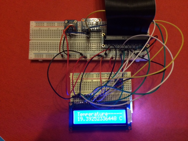
My first developments are ready. In short I created a java application that has to be installed on the Raspberry Pi which will read temperature and pressure from an Adafruit sensor (mpl1115a2) and showing reading on a small 16×2 LCD screen (Adafruit). As said in my previous post, I only used java technology and Pi4J. But in fact this is not 100% correct because behind the scenes, Pi4J is using a library called Wiring Pi. The wiring was simple once you know how to connect the pins to the LCD screen.
- First read about the installation steps for using and installing Pi4J
- To connect the LCD to the RP the following site was very useful : http://wiringpi.com/dev-lib/lcd-library/
- For the use of the barometric sensor (mpl115a2) I would like to refer to the site : Adafruit mpl115a2
- Information on LCD shield kit w/ 16×2 Character Display
- I did not use the shield. I did not manage to get it working using Java and the Pi4J api. I am sure it is possible but the complexity lays in the fact that the shield has an I2C expander and that made me give up in a first stage. I did get it working compiling one of the C Examples from the Wiring Pi site but my goal was to get it working via Java. I know, I am stubborn.
Components used
- breadboard (big enough)
- Raspberry Pi B+
- ADS1115
- mpl115a2
- LCD shield kit w/ 16×2 Character Display
- lots of wires
Tools used :
Important notice:
For the RP to be able to read from the sensor, an analog to digital (ADC) converter is necessary since the sensor only returns analog information. I have chosen for the I2C protocol so I needed an ADC which supported this protocol. For this project I used the ADS1115. It took me a while to understand but that was more related to the fact that I have no electronics background. But anyway, Google showed me the way to some interesting sites to get my knowledge in this context up to scale.
Lessons learned
- before using the sensor and lcd, make sure you have done all the soldering necessary. I made the mistake of not doing this in the beginning causing malfunction of the LCD but after soldering, all issues disappeared.
- Read the datasheets carefully.
- Doublecheck the wirings
- make sure you have a big enough breadboard
The source code is available on Github: https://github.com/jbyle/PI4JDevelopment.git
Comments of any kind are well appreciated, also source improvements.