PWM enable pins L298N

Hello readers,

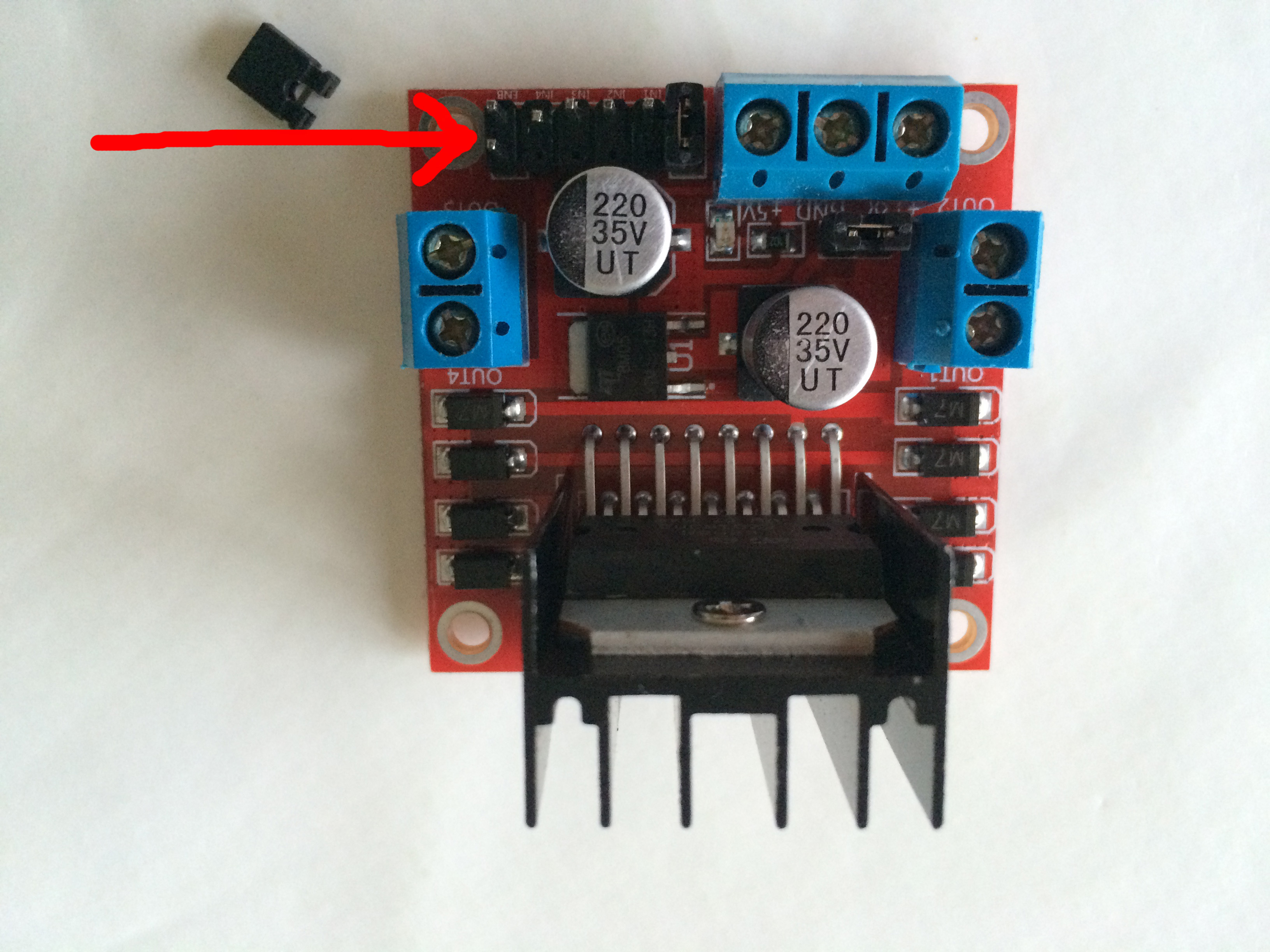
Trying out pwm pins to control the speed of the dc motors was not an easy story.  WiringPi has a software driven pwm handler which is used via PI4J.  In fact WiringPi is a GPI Access C library.  For more information see WiringPi.  The software handler makes it possible to have pwm functionality on all GPIO data pins on the raspberry pi.  There are also hardware pwm pins but there are only a couple of those dedicated hardware pins.  I have chosen to go for the software handled pwm pins.  What worried me was that the pin for the enable pin was not like the ones for the input pins (between the 2 enable pins) on the L298N.  I managed to get it wired but was not really satisfied because it didn’t fit right.  The result was that I could not manage at all the speed of the dc motors using pwm.  Whatever I tried in my little test program, it did not work work on the dc motors.  Just on the moment I was about to test with the hardware pwm pins, I found out there was a jumper on the enable pin, covering 2 pins.  At first sight when turning the L298N upside down, one pin was connected to the enable and the other pin had no real connection.  But since I am not a microchip nor electronics expert, that could be a wrong impression.  I connected 2 pwm (software handled) pins from the raspberry pi with the enable pins on the L298N which fitted right this time.  And guess what.  It worked.  I was able to increase and decrease speed of the dc motors.  Just like mentioned on the WiringPi site.

Shortly the pin wiring.  I am using the Raspberry Pi B+.  The port numbering is described at GPIO Port Numbering.

GPIO 0 -> enable A, GPIO 4 -> enable B, GPIO 2 -> input 1, GPIO 3 -> input 2, GPIO 5 -> input 3, GPIO 6 -> input 4, the output pins are wired to the dc motors, the battery (I used a 8,4V) positive wire is wired to the +V12 pin, the 3,3V power pin (Raspberry Pi) is wired to the +5V pin.  I know it sounds not logical +12V connected to 8,4V and +5V connected to 3,3V but it worked.  I bet my motor will turn like mad when I put higher voltage battery on it.

Jan

l298njumper

Pulse Width Modulation (PWM)

Hello folks,

I found a nice example on PWM in the PI4J project.  See PWM Example.  I tried it on my Raspberry PI B+.  I wired a little circuit with a led and tried it out.  It worked smoothly.  The led faded on and off which was the goal.  I had been trying this on my car based on the javadoc but it was not working so I needed a plain simple example to see how this PWM works and just to be sure it does work on my Raspberry Pi. Seeing this example immediately rang a bell why it was not working on the car.  I had configured and set the pulse in the enable pin but a little further in my application the enable pin was set high which I guess overruled the PWM setting.  I know what to change now and try it out.

Raspberry Pi Controlled Car : turn

Hello readers,

I managed to make my RPC (Raspberry Pi Controlled) Car turn.  But the result was not what I expected.  I had this great idea to let the front wheels turn in opposite direction for a fraction of a second.  Well how do I say.  The result was not what I hoped it to be.  The car turned but it turned in such a way that the Raspberry Pi and powerbank were literally thrown off the car and almost all cables were disconnected from the connectors.  What happened was that the turn was so violent that the car did a spin of 360°.  Not exactly what I wanted.  Even only turning 1 wheel without the other turning in opposite direction did not solve the issue.  I saw that the speed of the DC Motor was too violent in case the car is turning.  So I started reading and googling around and finally found that the L298N controller is able to control the speed of the dc motors.  What needs to be done is connect the enable inputs to an PWM (Pulse Width Modulation) cabable output from the Raspberry Pi.  For more information see the following link : PWM L298N.  I have understood that this is possible on Raspberry Pi and PI4J makes pwm available on all GPIO pins.  But as a former colleague of me always said : “The proof of the pudding is in the eating”.  I will go into detail on this and modify my program and make it support pwm.  I am curious.  I will let you know more as soon as I have done my first tests.  Maybe than will be a good time to package my code for the car and put it on GitHub.

Jan

Raspberry Pi Controlled Car : moving on

Hi folks,

after having assembled the car it was now time to move on.  The goal is to have a car that drives, not a car that collects dust. The last week I have been coding to get a nice set of functions to get the my car moving.  Not so long ago I already developed a piece of code to let a DC motor turn a wheel.  That experience I integrated in the current developments.  I had a strong limitation and that was the current I needed for my Raspberry Pi.  It was clear I needed a powerbank.  After some investigation I finally decided to order the XB101 Xtorm Power Bank Trip 9000.  I was a little worried about the 2.5 A current output from the powerbank knowing the Raspberry Pi needs maximum 2A.  Finally after a lot of googling came on a forum where somebody said that the Raspberry Pi only takes the amount current that it needs.  Another thing I was worried about was the 5V output.  I know the Raspberry Pi needs 5V but I was wondering what in case the powerbank was not able to give the full 5V and due to some loss (USB cable) only able to give 4.8V for example.  So I was looking for a powerbank with an output of 5.25V but didn’t find any.  Anyway I found some tests where the output was  also 5V and did not gave any issues for the Raspberry Pi.  After too much time of investigating and looking for information I finally ordered the powerbank yesterday evening.  And this morning it was already delivered.  My god what a great service.  I really hate running around in big stores looking for what I need.  I really prefer the internet.  It so much easier.  Now coming back on my developments.  I am now able to let the car move forward and backward by controlling 2 DC motors.  Let’s say  2-wheel drive.  Next step is making it able to turn.  There I will have to do some magic controlling the 2 DC motors to get this done.  Still thinking about the algorithm.  I am seeing a couple of possibilities but I have to test it first.

Before I forget.  I had to remove the cobbler and the breadboard because they were a real pain to get everything wired and placed on the car which was a big problem because the breadboard and cobbler took some place and were limiting me in my work.

About the source-code.  I will only publish once I have something that is presentable.  If you need the source about my current experiments earlier, please let me know and I can send it.

Jan

Raspberry Pi Controlled Car

Raspberry Pi Controlled Car